Skip to content

A landscape shaped by iron and water

The history of the Forges

At Buré, near Orval, buildings, remains and hydraulic works tell the story of an early ironworks. The 1842 plan and traces still visible make its organisation understandable.

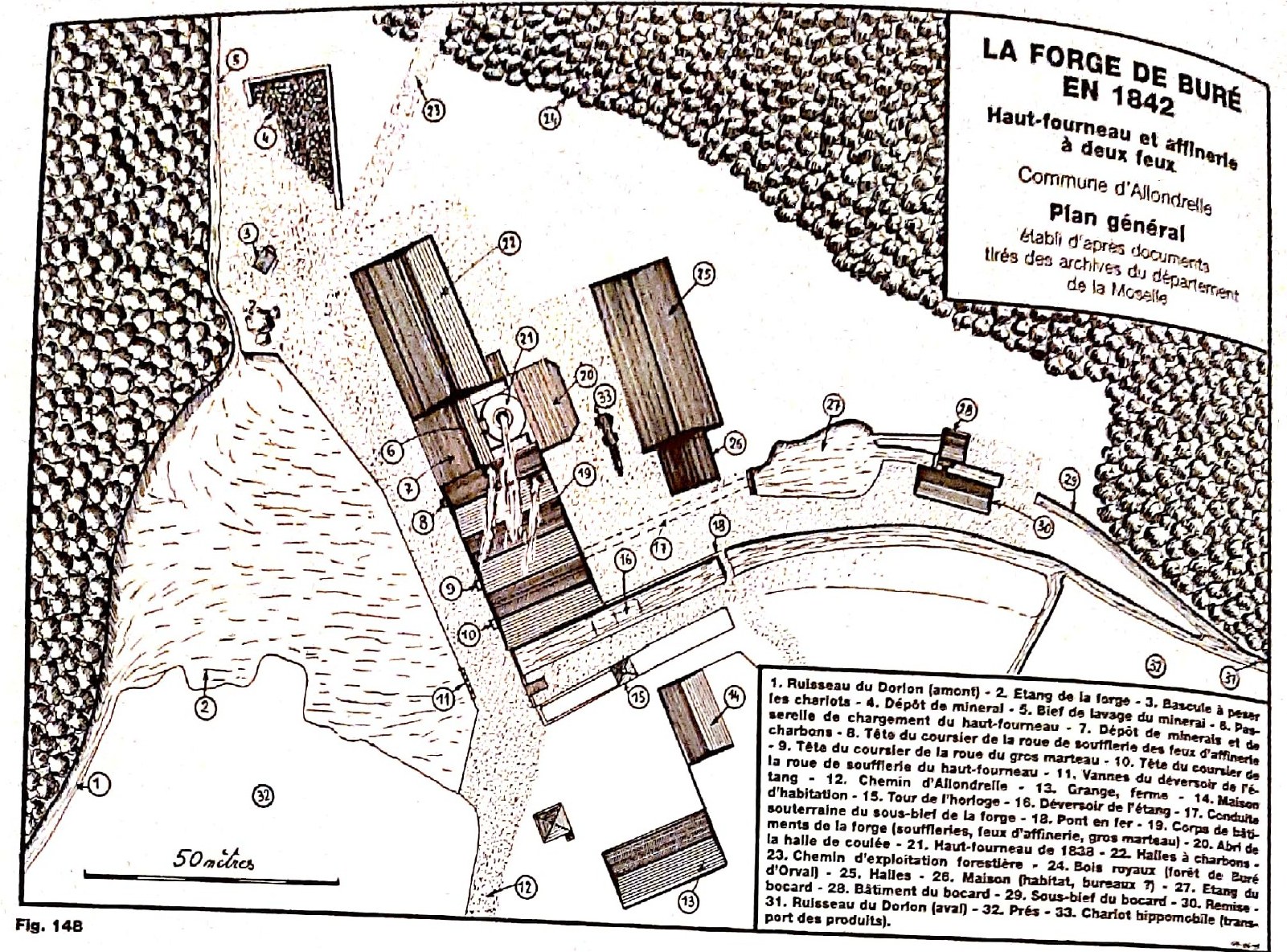
Drawn general plan of the Buré forge in 1842, showing the pond, buildings, headraces and numbered locations.

The Buré forge in 1842

General plan of the forge in 1842, locating the pond, dam, headraces, blast furnace, sheds, finery, plating mill and stamping mill.

Dalstein, ‘Buré la Forge’, fig. 148, PDF page 5, printed p. 112.

14th century — 1885

The site’s main milestones

A few landmarks follow the estate through change, rebuilding and industrial activity. Disputed dates remain clearly identified.

  1. 14th century

    The Cistercians of Orval founded the Buré establishment within their productive estate.

  2. 1692 / 1704

    As timber became scarcer, production shifted towards Dorlon. Records disagree on the end of the old Buré forge: this is a chronological uncertainty, not two successive closures.

  3. 1795

    The estate was sold as national property amid the transformations of the Revolutionary period.

  4. 1824

    The Trotyanne family took over the estate and began restoring it, subject to timber and water resources, neighbouring rights and administrative opinions.

  5. 1838

    The blast furnace was rebuilt; its surviving date stone remains the marker.

  6. 1842

    The general plan provides a snapshot of the site’s organisation, from pond to stamping mill. It shows only one blast furnace at Buré.

  7. 1860

    Openings in the great hall were altered while activity, affected notably by water constraints and economic conditions, was almost extinguished during the decade.

  8. After 1870

    The site experienced a revival before its final closure.

  9. 1885

    The furnace was put out of blast in a profoundly changed industrial landscape, without its closure being reducible to one certain cause.

1692 and 1704 mark uncertainty over the end of the old forge; Buré and Dorlon remain distinct sites, and the 1842 plan shows only one blast furnace at Buré.
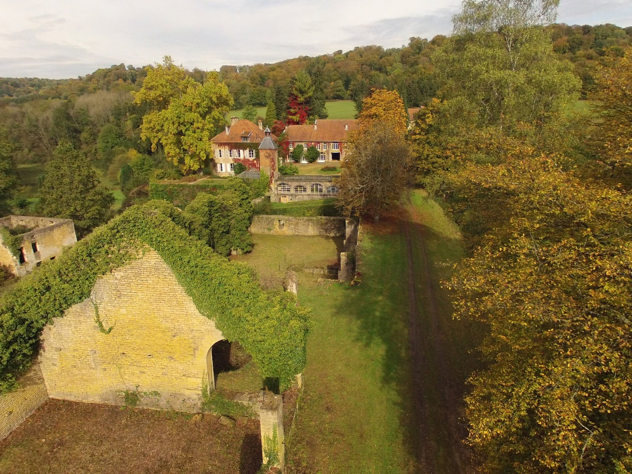
Aerial view of Les Forges de Buré d'Orval showing the buildings, tower, remains, meadow and wooded valley.
From above, the buildings, remains and meadow reveal how the site occupies the valley.

01 — Orval and iron

An abbey at the heart of a productive landscape

In the 14th century, the Cistercians of Orval founded the Buré establishment within their estate. It was more than one building: woodland, water, farmland, farms, furnace and working routes formed a productive territory.

Iron brought income while the estate gathered the essential resources. Woodland supplied timber for charcoal; pond and dam held water for the wheels; farms and tracks organised supplies.

Early sources connect Buré, Orval and Dorlon. Scarcer timber formed part of the context in which some production appears to have shifted to Dorlon in the late 17th or early 18th century. Records place the end of Buré’s old activity in either 1692 or 1704.

Buré and Dorlon nevertheless remain distinct sites. Keeping them separate explains what survives here without assigning neighbouring equipment to Buré.
02 — Rebuilding the site

The 1824 revival and the landscape of 1842

In 1824, the Trotyanne family took over the estate and began restoring activity. An ironworks depended as much on available timber and water, neighbouring rights and administrative opinions as on its workshops.

The surviving blast furnace bears the date 1838, a tangible marker of rebuilding. Four years later, the 1842 plan captured the site’s organisation in remarkable detail.

On arriving at Buré, this plan connects pond, dam, headraces, sheds, blast furnace, finery, plating mill and stamping mill. It shows only one blast furnace.

The buildings continued to change: openings in the great hall were altered in 1860. The site was a working tool adapting to use, not a frozen setting.

03 — A supply territory

From local ore to worked iron

Buré was connected to a small supply territory. Good-quality alluvial ore came notably from Saint-Pancré, Bois de la Butte, Aumetz and Athus in Belgium.

Ore and charcoal entered the blast furnace before pig iron moved to the finery. Repeated journeys between hearth and great hammer gradually turned this brittle material into workable iron.

The great hall concentrated a vital part of these operations. The surviving volumes now make sense as spaces shaped by a chain of handling, heat, air and motion.

04 — Distributing power

The pond unlocks the site

Pond and dam are more than scenery. Sluices regulated water sent to the wheels; the tailrace received it afterwards.

In the great hall, three wheels served the blast-furnace bellows, great hammer and finery-hearth bellows. Lower down, water could be reused at the stamping mill.

This motive power was available on site but depended on pond level, flow and season. At low water, machinery could slow and regional works sometimes stand idle.

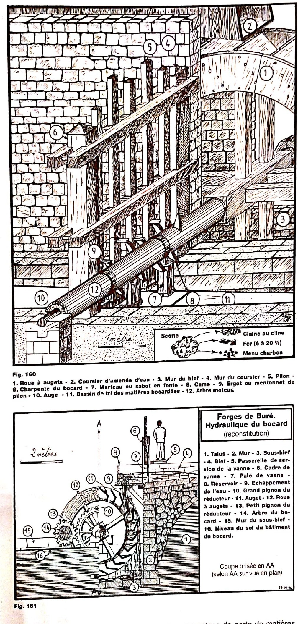
The stamping-mill section is a reconstruction: it clearly explains how falling water became motion without being an exact survey of every surviving part.

05 — Reading workplaces

Sheds, passages and machines

Approach track, charging bridges, ore and charcoal stores, casting shed and workshops formed a continuous working route.

The great hall brought together machines with connected functions. Some stood away from the equipment they served: a wind pipe could carry air from bellows to a hearth.

Plans clarify handling and material flows, but give neither workers’ names nor a secure headcount. Drawn figures provide scale only.

06 — An industrial world changes

The 1885 closure and today’s traces

In the mid-19th century, activity faced difficulties linked notably to water constraints and economic conditions. By the 1860s the site appears to have been almost extinguished, but its story was not a continuous decline.

After 1870, Buré experienced a revival. The furnace was finally put out of blast in 1885, in an ironmaking world transformed by the large Longwy works, coke and steam power, without one cause alone explaining the closure.

Buré nevertheless preserves a rare reading of the older system: buildings hold clues, the pond reveals the source of power and the 1842 plan reconnects scattered elements.

Documents, remains and reconstructions complement one another without being confused. Keeping this distinction lets visitors understand the place without turning hypotheses into certainties.

Understanding the work and machinery

How does an ironworks operate?

A large ironworks is a chain of operations. Material moves from ore to pig iron and then worked iron; alongside it, water transmits mechanical power to bellows, hammers and the stamping mill.

The path of the material

  1. Prepared ore
  2. Blast furnace
  3. Pig iron
  4. Finery
  5. Iron bloom
  6. Bar or plate

The path of energy

  1. Pond
  2. Sluices and headraces
  3. Overshot wheels
  4. Shafts, cams and gears
  5. Bellows, hammers, stamping mill
  6. Tailrace

Two distinct functions: charcoal provides the furnace heat; water sets the machinery in motion.

  1. Prepare the ore

    Good-quality alluvial ore came from nearby, notably Saint-Pancré, Bois de la Butte, Aumetz and Athus in Belgium.

    Learn more

    At the works it could be washed, sorted and crushed in the stamping mill. The machine also treated slag still rich in metal: two rows of four stamps broke it up, water carried away the lighter matter, and dense fragments rich in ore or metal were recovered by gravity.

  2. Make and store charcoal

    Made from woodland timber, charcoal was kept dry in a shed before feeding the blast furnace.

    Learn more

    It supplied the heat for smelting and took part in the reactions that transformed the ore. This thermal energy differed from hydraulic power: water drove the mechanisms but did not heat the furnace.

  3. Charge and blow the blast furnace

    Prepared ore and charcoal were raised to the throat—the opening at the top of the furnace—and loaded in layers.

    Learn more

    Bellows supplied air for combustion. Molten metal separated from slag, the material carrying impurities. Pig iron was tapped at the base towards the casting shed. Rich in carbon, it was hard and brittle, not yet the malleable iron required for bars.

  4. Refine the pig iron

    Pig iron was reheated in the finery hearth to reduce its carbon content and remove more impurities.

    Learn more

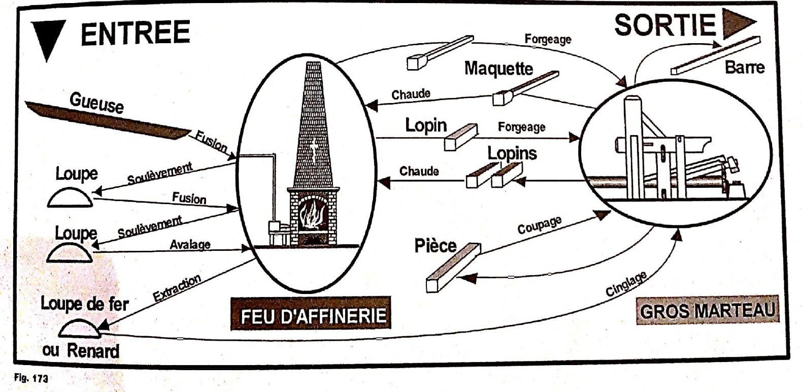
    This produced a bloom: a spongy mass of iron still mixed with slag. It was lifted from the hearth and carried to the great hammer.

  5. Shingle, reheat and shape

    Under the great hammer, the bloom was shingled: blows compacted it and forced out part of the slag.

    Learn more

    The piece could return several times to the hearth and hammer. It was progressively forged into a bar or plate. Figure 173 shows these repeated journeys; the process was not completed in a single pass.

  6. Distribute power in the great hall

    Three waterwheels served the blast-furnace bellows, the great hammer and the finery-hearth bellows.

    Learn more

    A machine was not always beside the equipment it served: air could travel through a wind pipe. Shafts, cams and gears transmitted motion. Water then entered the tailrace and could be reused downstream at the stamping mill.

  7. Work with the seasons

    Water provided motive power on site, but it depended on water level and flow.

    Learn more

    Pond level, flow and low-water periods directly limited the pace of machinery. When water ran short, regional ironworks could slow or stand idle; the hydraulic reserve therefore shaped the working calendar.

  8. Read Buré with care

    The plates make the process understandable, but they do not all have the same documentary status.

    Learn more

    The 1842 plan records the site layout. Some sections and elevations are reconstructions or possible states proposed by Dalstein. They explain machinery without becoming photographs of the past; the finery diagram presents a technical principle without proving every product made on site.

Two mechanisms at a glance

These simplified diagrams connect water, transmissions and workshops. They explain technical principles without claiming to restore every dimension or missing part.

The great hall and its three wheels

One water supply served three wheels, powering the blast-furnace bellows, the great hammer and the finery-hearth bellows. Wind pipes carried air to the hearths.

Simplified from historical documents and plans.

  1. Controlled water supply
  2. Blast-furnace bellows wheel
  3. Great-hammer wheel
  4. Finery-bellows wheel
  5. Blast furnace and casting shed
  6. Great hammer
  7. Finery hearths
  8. Wind pipes

The stamping mill: crush, wash, separate

The wheel turns the camshaft. Cams raise the stamps and release them over the trough. Water carries away light matter while dense fragments rich in ore or metal can be recovered.

Simplified working diagram; two distinct rows of four stamps.

  1. Reservoir
  2. Sluice and headrace
  3. Waterwheel
  4. Camshaft
  5. Two rows of four stamps
  6. Stamping trough
  7. Sorting grate
  8. Light material carried away

Short glossary

Throat
The upper opening of the blast furnace through which charges were introduced.
Pig iron
Carbon-rich metal made in the blast furnace, still too brittle to forge into bars.
Bloom
A spongy mass of iron leaving the finery before hammering.
Slag
Molten material containing impurities separated from the metal.
Stamping mill
A machine with stamps used to crush ore, slag or furnace waste.
Tailrace
The channel carrying water away after it passes a waterwheel.

Plates from the study

Reading the site through plans and sections

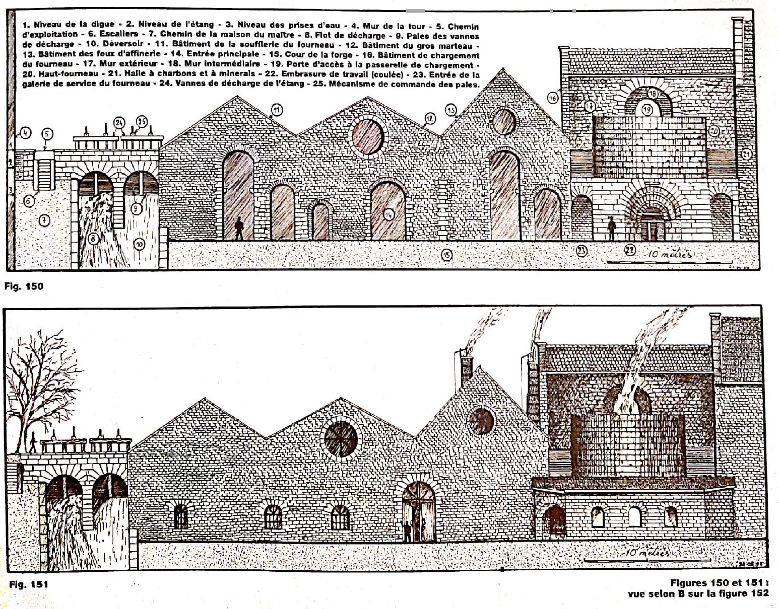
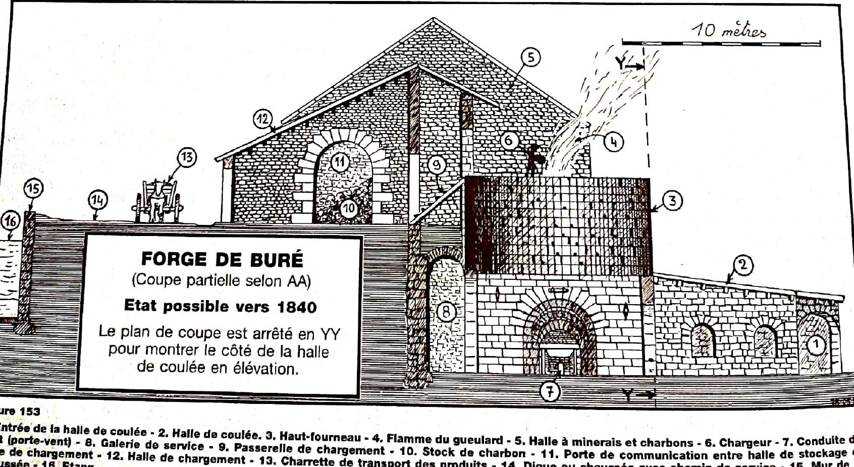
These plates from Dalstein’s work bring together plans, sections and elevations. They distinguish recorded documents from attempts to reconstruct states that have disappeared.

Two elevation drawings of the Buré forge buildings, showing façades, sluices and the blast furnace.

Elevations of the forge

Elevations and an attempted representation of the forge. These are the author's reconstructions, not historical photographs.

Dalstein, ‘Buré la Forge’, figs. 150–151, PDF page 6, printed p. 113.

Drawn section through the blast furnace and charging shed, with throat, footbridge and casting shed.

Section through the blast furnace

Partial section showing a possible state around 1840. The drawing is the author's proposed reconstruction.

Dalstein, ‘Buré la Forge’, fig. 153, PDF page 7, printed p. 114.

Two technical drawings of Buré's stamping mill showing the overshot wheel, drive shaft, stamps and water circuit.

The hydraulic stamping mill

The stamping mechanism and its hydraulic arrangement. Figure 161 is explicitly described as a reconstruction.

Dalstein, ‘Buré la Forge’, figs. 160–161, PDF page 14, printed p. 122.

Finery process diagram showing movement between the finery hearth and great hammer until an iron bar is produced.

From pig to bar

Diagram of product manufacture in the finery: material passes between the hearth and great hammer before leaving as bar iron.

Dalstein, ‘Buré la Forge’, fig. 173, PDF page 23, printed p. 131.